Purpose of the flight and payload description
Objective of the flight was to obtain direct solar images using a 10 CM SOLAR TELESCOPE SYSTEM designed to photograph the sun from a balloon platform in the stratosphere, where atmospheric turbulence would not degrade image quality. The project was carried out by the Tokyo Astronomical Observatory, Japan.
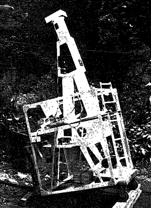
The optical setup of the telescope consisted of an objective lens, a semi-transparent mirror, a magnifying lens, and a camera arranged in sequence. The objective lens was a two-element achromatic design with an aperture of 100 mm and a focal length of 1,500 mm, ensuring sharp imaging across visible wavelengths. The semi-transparent mirror was made of fused quartz, 60 mm in diameter and 5 mm thick. This mirror had diverted a small fraction of light to a television system for monitoring, while the rest continued toward the magnifying eyepiece lens and the photographic camera. The magnifying lens was an orthoscopic eyepiece of 60 mm focal length, capable of fine focus adjustment along the optical axis within a ±2 mm range, controlled remotely in 0.2 mm increments. The final image was recorded with a Canon F1 camera equipped with a 250-exposure 35 mm long-film magazine made by Kasha for the Tokyo Astronomical Observatory. The camera's shutter could be operated by remote command, offering exposure times of either 1/500 or 1/2000 second, and its operation could be synchronized with other components. To minimize image blur from motor vibrations, the coelostats motor had been halted intermittently during exposures, ensuring stable imaging. Directly in front of the camera, a Toshiba VG54 color filter and an ND filter with three selectable densities divided the film frame into three zones to avoid over or underexposure. The semi-transparent mirror for the TV system reflected 30% of the incident light and measured 52.5 × 34.8 × 0.6 mm. The resulting solar image on the film was 17 mm in diameter, suitable for microfilm processing. The entire camera assembly was sealed in a waterproof case to withstand recovery from the sea.
The telescope's sunlight-tracking system was based on a 15 cm coelostat mirror made by Hoya Cristron, 15 mm thick, capable of ±10° movement in altitude and azimuth at speeds up to 1° per second. The photoelectric tracking device used two sensing stages: a coarse azimuth sensor employing a reset system and a fine sensor based on four solar cells arranged around the focused solar image. These cells detected imbalance in illumination and directed motor corrections to keep the Sun centered. In contrast with an earlier model that used a differential gear method causing unwanted vibrations, the improved system used only two motors, which remained almost stationary when balance was achieved, thereby reducing image blur. The entire tracking assembly could move laterally in four directions in the plane perpendicular to the optical axis, controlled by command, allowing any region of the solar disk to be centered on the film. For thermal protection, a Hoya HA50 heat filter and a Hoya UY49 color filter had been placed ahead of the tracking sensor.
A television imaging system for real-time monitoring and focus control enabled operators on the ground to visualize the solar image, position sunspots or the solar limb in the camera's field of view, and verify the focus by commanding fine adjustments of the secondary lens. The command and telemetry system used 12 command channels, 8 of which were allocated to the principal investigator's operations. Commands included those for image movement in azimuth and altitude, focus adjustment, exposure control, and mode switching. Telemetry data was transmitted through a 20-channel, 14.5 kHz system, which reported focus position, shutter speed, sensor outputs, mode status, and other operational parameters.
The entire optical assembly was mounted on an inverted V-shaped structure integrated into a gondola. The gondola's frame, measuring 870 × 870 × 2,300 mm, held the ballast tank at its center and surrounded it with power supplies, transmitters, and auxiliary devices. The lower rectangular section was insulated with foam polystyrene to protect against thermal fluctuations and impact during landing. The optical structure was connected to the gondola at three points through universal joints, isolating the telescope from shocks during balloon ascent and descent. Total payload weight was 183 kg, including 26.7 kg of ballast.
Details of the balloon flight
Balloon launched on: 9/12/1972 at 9:05 JST
Launch site: Sanriku Balloon Center, Iwate, Japan
Balloon launched by: Institute of Space and Astronautical Science (ISAS)
Balloon manufacturer/size/composition: Zero Pressure Balloon 5.000 m3
Flight identification number: B5-45
End of flight (L for landing time, W for last contact, otherwise termination time): 9/12/1972
The balloon was launched from the Sanriku Balloon Center, in Iwate on September 12, 1972. After a nominal ascent the balloon reached 29 km of altitude. Unfortunately, a malfunction in the reset sensor prevented the telescope from locking onto the Sun, resulting in only one usable exposure out of 250, capturing part of the solar limb. Post-flight analysis showed that the instrument had likely pointed away from the Sun for most of the flight, as inferred from temperature readings across various parts of the system. The camera temperature gradually decreased from +25°C to +5°C, confirming that no special thermal protection was necessary. Water condensation on the coelostat mirror and lack of focus adjustments contributed to the degraded image quality. Despite the failure to achieve continuous solar imaging, the experiment validated the robustness of the optical, mechanical, and telemetry systems.
External references
- Direct photography of the Sun using a 10-cm solar telescope (In Japanese) ISAS Departmental Bulletin Paper, Volume 9, Issue 1_B, pp. 268-272, (1973)
- Ten Years of Scientific Ballooning Activities in Japan (1966-1975) Tokyo University. ISAS: Bulletin, 12(2B):517-555, 1976
If you consider this website interesting or useful, you can help me to keep it up and running with a small donation to cover the operational costs. Just the equivalent of the price of a cup of coffee helps a lot.
