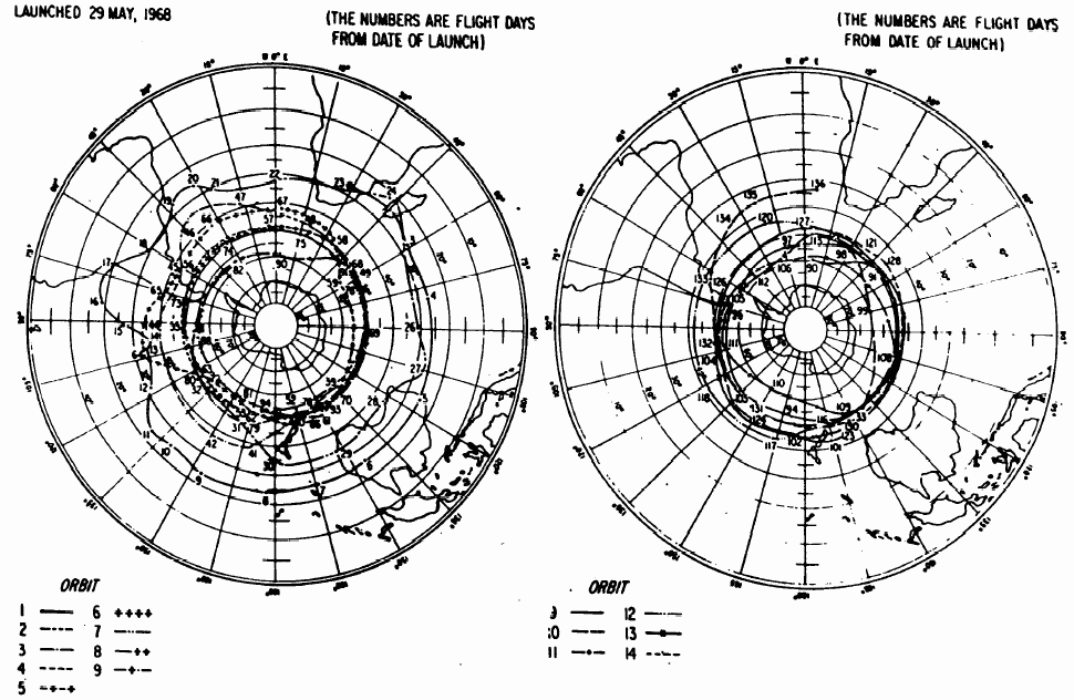
Purpose of the flight and payload description
The primary objective of the SOMEX II campaign was to observe X-ray and gamma ray emissions during solar flares. However, of considerable additional importance was a study of the balloon performance itself, and of meteorological data obtained. The initiative was under coordination of the Laboratoire de Météorologie Dynamique with funding from the Centre National de la Recherche Scientifique (CNRS) from France.
For these flights, were used superpressurized Mylar balloons manufactured by Raven Industries from USA that had a diameter of 4 meters. They were capable of carrying a 500-gram payload.
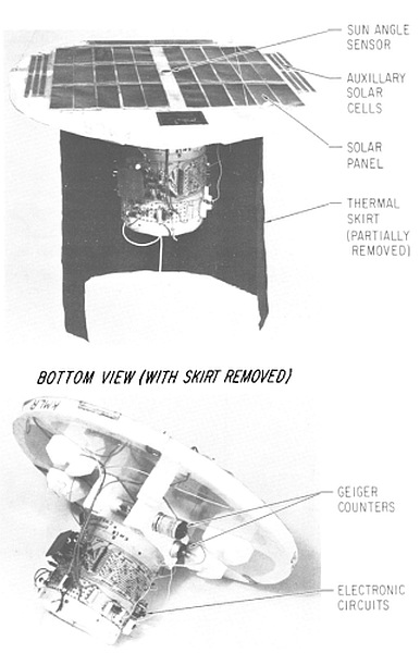
In the image at left we can see a description of the paylod (click to enlarge). The main scientific equipment were two Geiger counters aimed to monitoring the secondary radiation at an altitude of 55,000 ft. Aditionally was also included one photoresistive element for the measurement of the solar elevation angle and thus of the position of the balloon; one thermistor for the measurement of temperature. All power was generated by a small solar board of Cadmium sulfide cells that delivered up to 2.5 watts during the day (there were no measurements performed during nighttime).
Taking account that this experiment was performed before the development of satellite-based location systems, the method that has been used to locate long-duration balloons during GHOST, EOLE and SOMEX I experiments was to measure the solar elevation during the daylight hours and then compute the balloon position at local noon: latitude by the noon solar altitude and longitude by the time of balloon noon. This method required a lengthy series of measurements during the day and has degraded accuracy when the maximum solar angle approached 90º. Thus, another method was therefore devised for SOMEX II in which the solar angle data were complemented by data that indicated the local geomagnetic rigidity; the correlation of the two data yielded an improved position determination algorithm. This method was applied to the trajectory determination of the SOMEX balloons with considerable success.
The measuring sensor (solar elevation detector, for example) controled the frequency of an oscillator. The oscillator frequency feeded a Morse code letter forming circuit, such that the repetition rate of the Morse code letter being formed was a monotonic function of the input frequency. This signal was then used to key a HE transmitter (generating 100 to 1000 mW RF power). Since four independent measurements were made in these flights, an onboard programme sequenced the sensors so that each was monitored continuously for 30 sec. Each balloon was identified by its particular group of code letters.
The signals were received at stations of the French and NCAR balloon tracking networks around the southern hemisphere. There, each received signal was processed manually: an operator identified a balloon by its code letters and measured the rate of letter transmission with a stopwatch. This process was continuously repeated as long as there were balloon signals being received. The tracking range of an individual station varied from 3,000 to 12,000 miles, depending upon station equipment, operator acuity, and HF reception conditions. The data was manually recorded on standard forms and then transmitted to the data reduction center in Paris.
Details of the balloon flight

Balloon launched on: 5/29/1968
Launch site: Paardefontein Tracking Station, Pretoria, Southafrica
Balloon launched by: Centre National d'Etudes Spatiales (CNES)
Balloon manufacturer/size/composition: Super Pressure Balloon Raven - Mylar - 4 meters of diameter
Flight identification number: VMWR
End of flight (L for landing time, W for last contact, otherwise termination time): 10/12/1968
Balloon flight duration (F: time at float only, otherwise total flight time in d:days / h:hours or m:minutes - ): 136 d
Nominal flight
External references
- New experimental description of the geographical temperature distribution in the Southern Hemisphere near the 100-millibar level during winter and spring Journal of Geophysical Research, 74(28), 7038
- Position determination methods used to track superpressure balloons Monthly Weather Review Volume 98, Issue 10 (October 1970) pp. 756-764
1738If you consider this website interesting or useful, you can help me to keep it up and running with a small donation to cover the operational costs. Just the equivalent of the price of a cup of coffee helps a lot.


