
Purpose of the flight and payload description
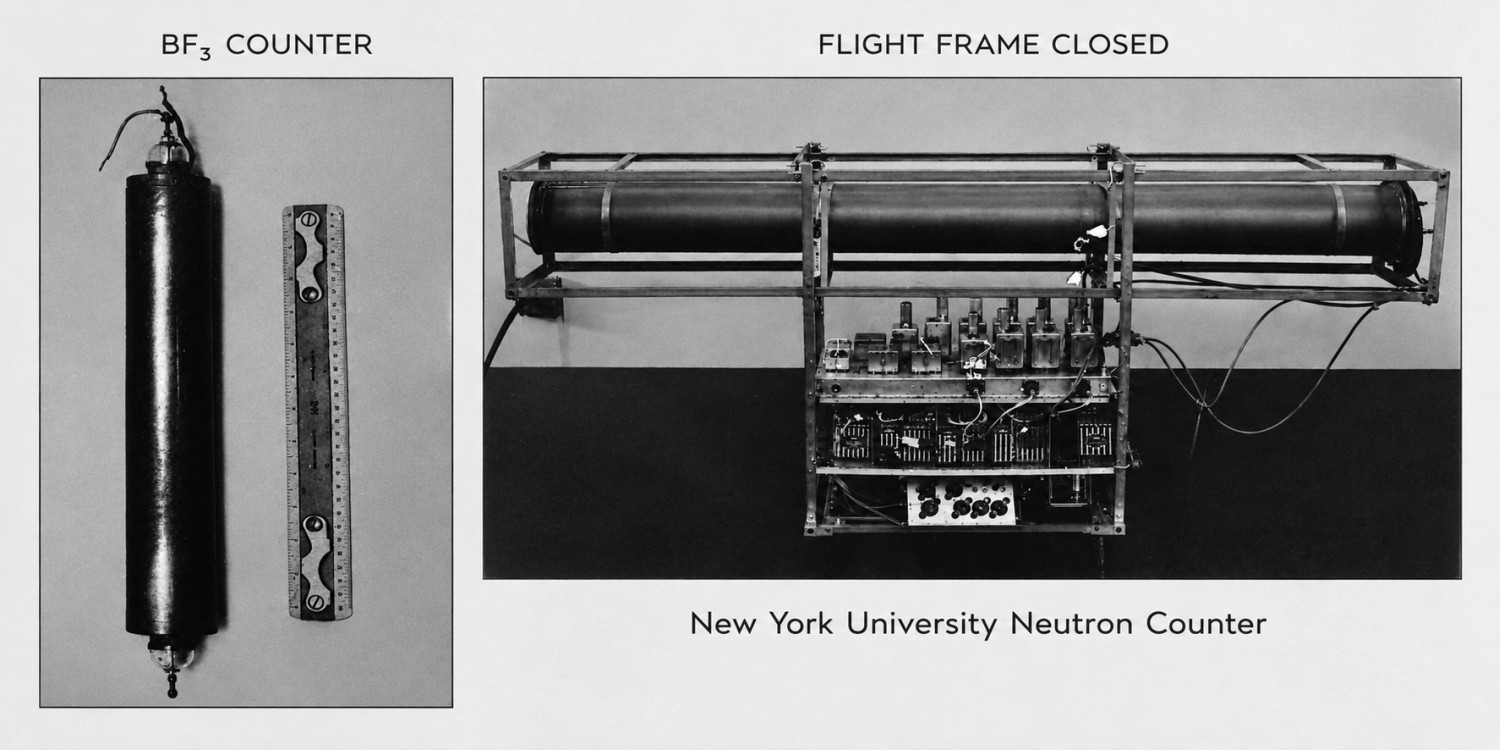
The objective of the flight was to measure atmospheric neutron intensities using a balloon-borne NEUTRON COUNTER designed by the Research Division of the College of Engineering of the New York University in the early 1950s. The instruments core consisted of two boron trifluoride (BF3) proportional counters, identical in construction and filled to the same gas pressure, but differing in isotopic composition. One counter contained isotopically enriched BF3 with a high proportion of boron-10 (10B), while the other contained isotopically depleted BF3. This configuration enabled neutron-induced events to be distinguished from background signals associated with cosmic-ray interactions and other sources.
In the picture at left we can see one of the detectors in its container frame (click for more details). The detection principle was based on the interaction of neutrons with boron-10 nuclei in the BF3 gas. These interactions produced electrical pulses in the proportional counters, which were collected at the central wires. The outer cylinders were maintained at a high negative voltage, while the central wires operated near ground potential. The resulting pulses were transferred through hermetic electrical feedthroughs to the signal-processing electronics.
The two counters were connected to a switching system operated by a program motor and a cam-driven microswitch. This mechanism alternately connected each counter to the readout electronics for predetermined intervals. The switching system also generated distinct signals identifying the active counter, allowing measurements from both detectors to be distinguished in the transmitted data.
The electronic readout chain comprised a cathode-follower preamplifier, a two-stage resistance-coupled amplifier, a pulse-scaling circuit, and a trigger circuit. The preamplifier provided impedance matching between the proportional counters and the amplifier. The amplifier increased the pulse amplitude, while the scaling circuit reduced the pulse rate presented to the trigger stage. The trigger circuit actuated a blocking oscillator that modulated the radio transmitter, enabling the detection events to be recorded at ground stations. The transmitted signal was received and recorded using a radio receiver connected to a pen oscillograph.
The counters and high-voltage components were enclosed in a pressure-tight assembly to prevent corona discharges under the reduced atmospheric pressures encountered at high altitudes, which could otherwise produce spurious counts. The assembly incorporated sealed connections for the high-voltage and signal lines. The instrument was mounted on a welded aluminium flight frame, with the counters aligned longitudinally to minimize the solid angle subtended by one counter upon the other and to reduce the amount of scattering material above the detectors. The electronic components were individually mounted to facilitate replacement during field operations, and the circuitry was enclosed in copper screening to reduce external electrical interference.
Details of the balloon flight
Balloon launched on: 9/8/1953 at 10:08 CST
Launch site: USS Currituck (AV-7)
Balloon launched by: General Mills Inc.
Balloon manufacturer/size/composition: Zero Pressure Balloon General Mills 85
Flight identification number: GMI 1076
End of flight (L for landing time, W for last contact, otherwise termination time): 9/8/1953
Balloon flight duration (F: time at float only, otherwise total flight time in d:days / h:hours or m:minutes - ): 4 h 10 m
Landing site: In Albemarle Island at 0º 25' S 91º 5' W
Campaign: OPERATION CHURCHY
Payload weight: 153 lbs
The balloon was launched at 10:08 A.M., CST on September 8, 1953. This flight, which used an 85-foot polyethelene balloon, was launched from geographic position 00° 16'S and 90° 19'W. The balloon rose at approximately 600 ft/min to an altitude of 20.000 ft. At this altitude the rate of rise increased to about 1000 ft/min until an altitude of 84.200 ft was reached, where the balloon leveled off and floated for the next two hours. At the end of this time, the signal-to-noise ratio decreased to the point where the transmitter signal became completely unintelligible. It is believed that the clock-operated squib must have cut the flight frame loose on a parachute at that time (since the flight frame was seen to come down during the next 30 minutes), and in the shock of being dropped, the transmitting antenna was shorted to the frame. However, useful data were recorded for the 3.8 hours during which the balloon rose and floated at altitude.
External references
- High Altitude Cosmic Ray Neutron Intensity Variations Prepared for Office of Naval Research, Nuclear Physics Branch, Washington, D.C., Contract No. N6 onr 279 TO 2
- High-Altitude Cosmic-Ray Neutron Intensity Variations Phys. Rev. 102, 1399 (1956)
- Project Skyhook - Final report projects 85022 and 85023 General Mills Mechanical Division - Report Nº 1434 - July 1955
StratoCat is an independent, non-commercial project maintained to preserve and share the history of scientific and stratospheric ballooning. If you find the site useful, you can help keep it running with a small donation toward its operating costs. Every contribution, even the equivalent of a cup of coffee, is greatly appreciated.