Purpose of the flight and payload description
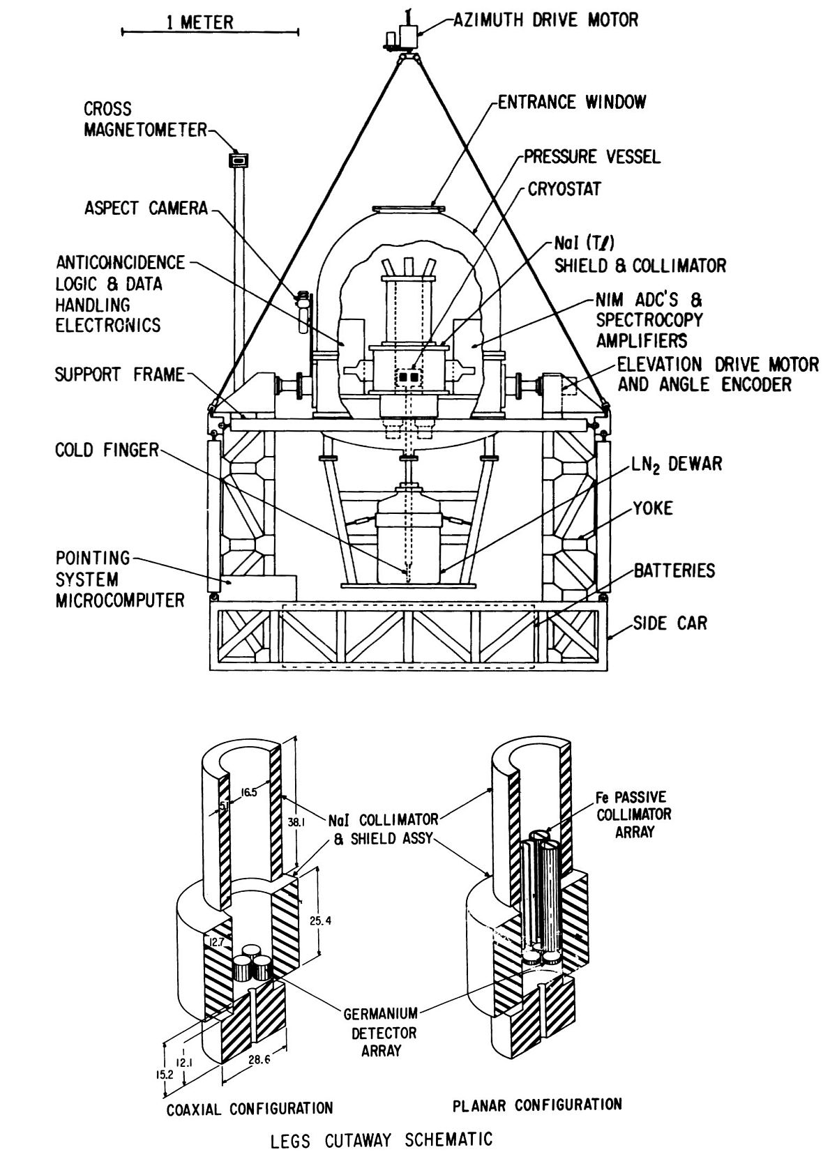
The Low Energy Gamma-ray Spectrometer (LEGS) was a joint project among NASA's Goddard Space Flight Center (GSFC), Centre d'Etudes Nucleaires de Saclay (CENS) from France and Rice University designed to perform fine energy resolution measurements of astrophysical sources. The instrument could be configured for a particular balloon flight with either of two sets of high purity germanium detectors. In one configuration, the instrument used an array of three coaxial detectors (effective volume 230 cm3 ) inside an Nal (Tl) shield and collimator (field-of-view - 16° FWHM) and operated in the 80-8000 keV energy range. In the other configuration, three planar detectors (effective area 53 cm2 ) surrounded by a combination of passive Fe and active NaI for shielding and collimation (field-of-view 5° x 10° FWHM) were optimized for the 20-200 keV energy range.
A cross-sectional view of the LEGS gondola is shown in the figure at left. A cryostat containing the detector array was the heart of the system and was mounted inside an active anticoincidence shield which consisted of about 190 kg of Nal scintillator in three sections viewed by a total of 24 photomultiplier tubes. The three sections of the shield fit together in such a way as to provide between 30 and 60 g/cm 2 of Nal between the detectors and non-aperture photons.
The spectrometer and associated electronics (anticoincidence logic, detector and shield pulse height analyzers, digital telemetry encoder, and command distribution system) were enclosed in a sealed aluminum pressure vessel which maintained these subsystems at atmospheric pressure. A stainless steel dewar was mounted in a cage attached below the pressure vessel. It held ~ 25 liters of liquid nitrogen for cooling of the germanium detectors. This was enough to keep the detectors at operating temperature (- 100 K) for about one week. The thermal interface to the detectors was a copper cold finger enclosed in an evacuated stainless steel jacket. A hole in the rear shield section allowed the cold finger to reach the dewar. A gasket around the stainless steel jacket prevented air leakage at the point where the cold finger entered the pressure vessel. The dewar was also sealed to prevent the liquid nitrogen from freezing at float altitude. A pressure relief valve allowed boil-off of nitrogen while maintaining approximately one-third atmospheric pressure in the dewar.
Thermal control of the spectrometer was accomplished by encasing the pressure vessel in two inches of ethafoam insulation and by isolating the pressure vessel from the gondola using epoxy fiberglass bushings at the experiment attachment points. Auxiliary resistance heaters were also available for use in extreme conditions. The experiment was mounted in an azimuth-elevation configuration in an open-frame gondola consisting of a U-shaped yoke, support arms, and "sidecars". These sidecars were not part of the primary load-bearing structure, but rather functioned as supports for various gondola subsystems such as batteries and control electronics. The sidecars also provided some shock absorption on landing and were designed to be conveniently repaired and/or replaced.
The attachment points of the pressure vessel constituted the axis about which the telescope was rotated in elevation. The elevation angle was measured using a digital shaft angle encoder coupled directly to one of the pivot points. This pivot point was connected through a gear box to a small DC motor which controled the elevation angle. The experiment could be rotated approximately 60° in either direction from vertical. Four stainless steel cables connected the corners of the gondola to a single attachment point, above which was a drive motor which rotated the entire gondola in azimuth. The azimuth of the experiment was determined using a specially designed cross magnetometer. Two such units were flown for redundancy, one mounted on a boom at the top of the yoke and one mounted on a sidecar near a corner of the gondola.
Instrument pointing was controlled by an onboard microcomputer based on a Texas Instruments TMS9900 microprocessor. Latitude, longitude, target right ascension, target declination, and local magnetic deviation were entered by telecommand from the ground and the computer periodically calculated and updated the azimuth and elevation of the target and drove the control motors appropriately. The computer handled interpretation and distribution of digital telecommands, including commands to the spectrometer system electronics. The pointing microcomputer was mounted on the sidecars, as were other subsystems which handle power distribution and telecommand interface functions. Lithium batteries capable of supplying approximately 60 hours of operation were also mounted in the sidecars.
Verification of the pointing system performance was accomplished at night using a star camera mounted on the experiment pressure vessel. The motorized camera had a 500 ft. magazine which held enough film for ~ 4000 pictures. Exposures were synchronized to a clock derived from the telemetry encoder. A sun-azimuth sensor (mounted on the gondola frame) was constructed for daytime verification of the pointing.
Details of the balloon flight
Balloon launched on: 11/20/1981 at 4:20 local
Launch site: Australian Balloon Launching Station, Alice Springs, Australia
Balloon launched by: National Scientific Balloon Facility (NSBF)
Balloon manufacturer/size/composition: Zero Pressure Balloon Winzen 746.432 m3 (12.70 Microns Stratofilm)
Balloon serial number: W26.36-2-03
Flight identification number: 180N
End of flight (L for landing time, W for last contact, otherwise termination time): 11/20/1981 at 3:34 local
Balloon flight duration (F: time at float only, otherwise total flight time in d:days / h:hours or m:minutes - ): 19 h
Landing site: 300 miles W of Alice Springs, Australia
Payload weight: 1452 kgs
This was the sixth and last flight of the instrument. Detector configuration used was Coaxial. The main purpose of this flight was to study the region of the galactic center in the gamma-ray range. In particular were made high resolution spectroscopic measurements aimed at the detection and study of narrow lines in the gamma-ray spectrum. This was accomplished using an array of three cooled Germanium detectors having a typical energy value of several hundred in the MeV range.
External references
- A balloon-borne instrument for high-resolution astrophysical spectroscopy in the 20 - 8000 keV energy range NASA technical report NASA-TM-85011, NAS 1.15:85011
- Gamma-ray spectroscopy of the galactic center region - Confirmation of the time variability of the positron annihilation line Astrophysical Journal, Part 2 - Letters to the Editor, vol. 260, Sept. 1, 1982, p. L7-L10
- High Energy Resolution Experiment in the Hard X-Ray Range 18th International Cosmic Ray Conference, 1983. Vol.9, p.335
- National Scientific Balloon Facility Annual Report FY 1982 National Center for Atmospheric Research, February 1983
- Observations of the galactic center with the GSFC Low-Energy Gamma-Ray Spectrometer: Preliminary results AIP Conference Proceedings 83, 139 (1982)
- The gamma-ray spectrum of Centaurus A: A high-resolution observation between 70 keV and 8 MeV NASA-TM-85081, NAS 1.15:85081
- Upper limits to the annihilation radiation luminosity of centaurus A AIP Conf. Proc. 101, 309 (1983)
4623If you consider this website interesting or useful, you can help me to keep it up and running with a small donation to cover the operational costs. Just the equivalent of the price of a cup of coffee helps a lot.
About StratoCat
Some Statistics
+ 20 articles from different contributors
+ 15395 balloon launch records already published
+ 15671 balloon launch records in the full database
StratoCat is a non-profit, educational and informative website created, developed and programmed by Luis E. Pacheco. It is based on an idea first conceived by the author in 2001 and is online since September 17th, 2005.
This website is an independent initiative, and thus is not endorsed, supported or have any relationship with any governmental or private agency or company in the balloon field.
Page generated on 20-Apr-2024 - 06:44:45pm  © StratoCat 2005~2023 - All Rights Reserved.